Many organisations are still stuck in the old paradigm when preparing a data center tender, not knowing the industry has moved significantly since the last time they went to tender, and in some cases not knowing what new technologies are available and how that would actually better suit their organisation’s needs.
One such advancement in data center design is the modular data center. The scalability, agility and portability of a modular data center system means a modular system can meet any data center requirement.
Let’s take a look at proximity, power and tier certification issues considered in a medium density data center tender relocation project.
Proximity
Many tenders require a facility to be located near or within a specific radius of a given location. The portability of a modular data center system, like the Datapod System, means the facility can be placed in any prepared site location. Locations can include greenfield sites, roof top spaces (with appropriate load bearing capacity), as well as other inner city or urban locations, indoors or out. Furthermore, the scalability means the data center can be added to either vertically or horizontally at a later date – extending the life and functionality of the data center while lowering the overall cost.
Proximity also dictates accessibility to other services, such as:
– Fibre paths
– Carriage services
– Power utility
– Road access
– Rail access
– Water supply
NB: with the addition of the Utilitypod, and access to satellite services the Datapod System can be deployed to remote locations that do not have access to a power utility. This makes the Datapod System attractive for defence, mining or humanitarian locations.
Rack /Kw range for example, 3Kw, 5Kw, 7kW, 12kW, 15kW, 20Kw, 30kW
Modular systems can be configured to a number of different densities for example:
Rack power capacity based on commonly available circuit breaker sizes or combinations of breakers, ie:
- (1ø)16amp (3.7KW),
- (1ø) 32amp, (7.4KW),
- (3ø) 16amp (11.1KW)
- (2×1ø) 2 x 32amp (14.8KW),
- (3ø) 32amp (22.2KW) and
- (3ø)32amp and (1ø)32amp (29.6KW).
All racks have dual path power supplies from separate UPS system supplied by divergent Sub-Distribution Boards and UPS’s.
The Datapod System can also meet requests for a contiguous environment by providing a central non-ICT work (Entrypod) area which can separate two datahalls each containing up to 40 racks or the Entrypod can be positioned to one side with a single contiguous data hall. The modular nature of the system mean modules can be placed to suit customer.
Power and cooling capacity including the computer room power distribution solution, any supplementary cooling, and redundancy levels being provided
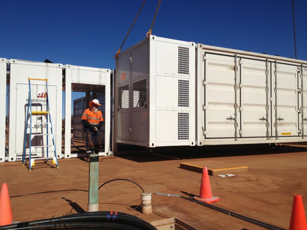
The Connection Node is the point of entry for all utilities (power, water, communications) into the Datapod System, and contains the electrical Mains Distribution Boards (MDB) as well as secondary water pumps in discreet isolated chambers.
The electrical boards in the Connection Node will each take fully rated mains incomer, as well as a backup input from a Utilitypod/s via inbuilt Automatic Transfer Switch (ATS).
The MDB’s also incorporate Transient Voltage Surge Suppression (TVSS). Filtered mains (or generator power) is routed across to the datahall module where it supplies dual redundant UPS systems.
Each Starterpod is provisioned with dual modular UPS’s to meet the typical ICT requirements as well as supporting Essential Services Distribution Boards which support items such as the Fire Panel, emergency lighting and Inrow Cooler fans.
Power from the UPS is distributed by Inrow Power Distribution Units (IR-PDU’s) which are positioned in mid-row. Each rack within the datahall is powered by both IR-PDU’s, with 100% capacity available from each to support the design load. Racks can be provisioned or as required with dual metered PDU’s. In addition, each Starterpod is also fitted with a Non-Essential Services Distribution Board for non-critical items.
Mechanically, for a medium density project, the Datapod System would be cooled via chilled water (CW) produced by the modular chillers located within the dual Utilitypods. The modular chillers are configured in an N+1 array within the Utilitypod.
CW is distributed via a common header arrangement located within the Starterpods. Each header includes supply and return outlets, and routes chilled water to the Inrow coolers located between the IT racks.
The central ‘Hot Aisle’ between the two rows of IT racks is contained using an insulated roof kit enabling all warmer exhaust air to be ‘captured’ and drawn back into the Inrow cooler intakes, where the waste heat is stripped out across cooling coils. The waste heat is then carried back to the heat exchange fancoil units located in the Roof mount Assembly module situated on top of the Utilitypod.
The fancoil units are provisioned in the same quantity/redundancy as the chiller/compressor units within the Utilitypod, for example N+2. In addition to the main air-conditioning system for the datahall, we provision the Entrypod with a Direct-Expansion (DX type) comfort cooling air-conditioning system. This non-redundant system is designed to condition the Entrypod non-IT workspace, and also to route some air into the datahall to replenish air and positively pressurise the environment against ingress by airborne contaminants.
Compatibility with the (minimum) Tier III standard
Being a modular system composed of interoperable modules it is possible to design a Datapod system to achieve any Tier level of redundancy.
For example, a highly resilient Tier 3 design can be configured using dual/diverse mains inputs, dual/redundant generators, chillers and UPS’s per datahall. Inrow coolers are similarly configured in a 2N arrangement.
Mechanically, arrays of modular chillers support each datahall, providing 2N redundancy. Their output is routed via diverse paths to header arrangements at opposite ends of the datahall/s and is then distributed to the redundant Inrow coolers.
Electrically, two separate Mains Distribution Boards support each datahall, and feed different UPS systems each capable of supporting the entire load, ie configured in a 2N arrangement. Dual redundant diesel generators support each datahall.
The redundant UPS’s separately provision each IT rack with power in a ‘system + system’ approach, such that if one side were to fail or be taken offline, the 2nd supply would support the entire load with an earth mat deployed around the Datapod System.
Each datahall is provisioned with its own fire suppression system, incorporating inert gas (IG-541) suppression activated by two-stage sensing (VESDA) and ionising smoke detector.
Security for the Datapod System begins with external and internal CCTV cameras. IP (digital) high-definition colour cameras are deployed at both ends of each internal aisle within the datahalls, and on both sides of the Entrypod enabling clear visibility of anyone entering or working within the facility.
Externally, a combination of fixed dome colour high-definition digital cameras and PTZ cameras are provisioned on all sides of the facility to ensure that no-one is able to approach the facility without being seen. The cameras are capable of working in low-light using IR capability, and lighting around the Datapod further enhances the capability of ensuring facial recognition of all who approach the facility. The entrances to the Datapod are physically secured by solid core door system, augmented by reed switches linked to the IMCS.
Describe the Data Center facility building(s) by detailing the structure and design
Despite appearances, the datahall modules (and Entrypod) are not constructed out of shipping containers.
The Datapod System is purpose designed and are sized specifically in order to achieve certification under ISO-668 and ISO R-1161 standards for classification of containers in order that Datapod can meet the global logistics and transport industry that has been created specifically to manage this type of module.
Having the form-factor, ISO certification and American Bureau of Shipping (ABS) approvals allows the Datapod modules to be easily and cheaply transported and positioned anywhere. Functionally however they were designed from ‘day 1’ to be a datahall, as is demonstrated by the interior construction.
With 110mm thick highly insulated walls, lined with stainless steel and fully electrically isolated from the exterior skin of the module, the Datapod System is designed to provide Faraday-cage properties, making it an ideal environment for ICT systems.
Each of the datahall modules is 20’ (6m) in length and falls into one of four broad categories:
- Entrypod – non-IT environment for a variety of convenience functions, separated from the datahall by a glass partition wall/doors.
- Starterpod – the initial ‘starting point’ of the datahall, containing the electrical and mechanical connections and distribution systems, as well as a variety of other critical sub-assemblies. The UPS is typically housed in the Starterpod. For 2N arrangements, two Starterpods (or a single 2N version) can be deployed at either end of a single datahall.
- Expanderpod – typically containing racks and Inrow cooling units, and pre-deployed with all necessary sub-assemblies such as lighting, services conduits (fire, water, etc) and overhead cable tray. Any quantity of Expanderpod can be added to a Starterpod.
- Endpod – typically the final module, containing racks and Inrow Coolers but terminating with a sliding door to cap off the end of the ‘hot-aisle’. The Endpod can be deployed with a removable end wall to enable further expansion if required. In the Bankwest design, due to the Tier 3 requirements no Endpod is required (replaced by a 2nd Starterpod).
The various datahall modules are joined together by a patented joining mechanism, to enable an environment of any size to be created. Being constructed primarily of steel, at the end of useful life the Datapod modules can be almost fully recycled.